1
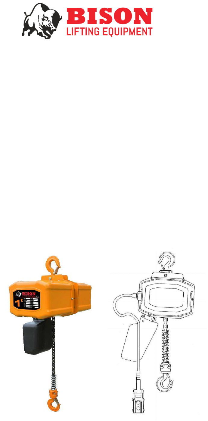
ELECTRIC CHAIN HOIST
OPERATING AND
MAINTENANCE MANUAL
(Capacity: 1/4~5T)
Single Phase/115~230V 60HZ
2
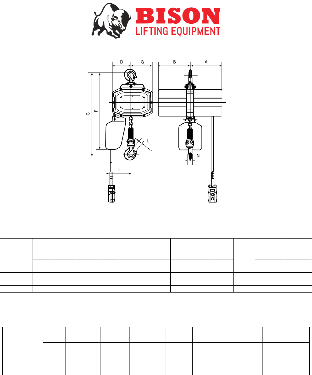
Product Code
Cap.
Head Room
(C)
A
B
G
D
L
F
H
N
Ton
Inches
Inches
Inches
Inches
Inches
Inches
Inches
Inches
Inches
HH-B025
1/4
21.5
10
10
7
6
1.47
22
8
0.73
HH-B05
1/2
21.5
10
10
7
6
1.47
22
8
0.73
HH-B10
1
22.8
10
10
7
6
1.47
24
8
0.73
Product
Code:
Cap.
Standard
Lift
Height
Lifting
Speed
Motor
Output
Power
Supply
Control
Voltage
Rated Current
(amps)
Load
Chain
Size
Chain
Fall
Lines
Pendant
Cord
Length
Total Net
Weight
Tons
Ft.
Ft.
/min
Hp.
Volts (1-
Phase)
Volts
@115v
@230v
mm
Ft.
Lbs.
HH-B025
1/4
20
21
1.3
115/230V
24
9.8
4.9
7.1
1
17
148
HH-B05
1/2
20
21
1.3
115/230V
24
9.8
4.9
7.1
1
17
148
HH-B10
1
20
21
2
115/230V
24
14.2
7.1
7.1
1
17
150
¼, ½, 1 TON
3
Product
Code:
Cap.
Standard
Lift
Height
Lifting
Speed
Motor
Output
Power
Supply
Control
Voltage
Rated Current
(amps)
Load
Chain
Size
Chain
Fall
Lines
Pendant
Cord
Length
Total Net
Weight
Tons
Ft.
Ft.
/min
Hp.
Volts (1-
Phase)
Volts
@115v
@230v
mm
Ft.
Lbs.
HH-B20
2
20
10.5
2
115/230V
24
14.2
7.1
7.1
2
17
173
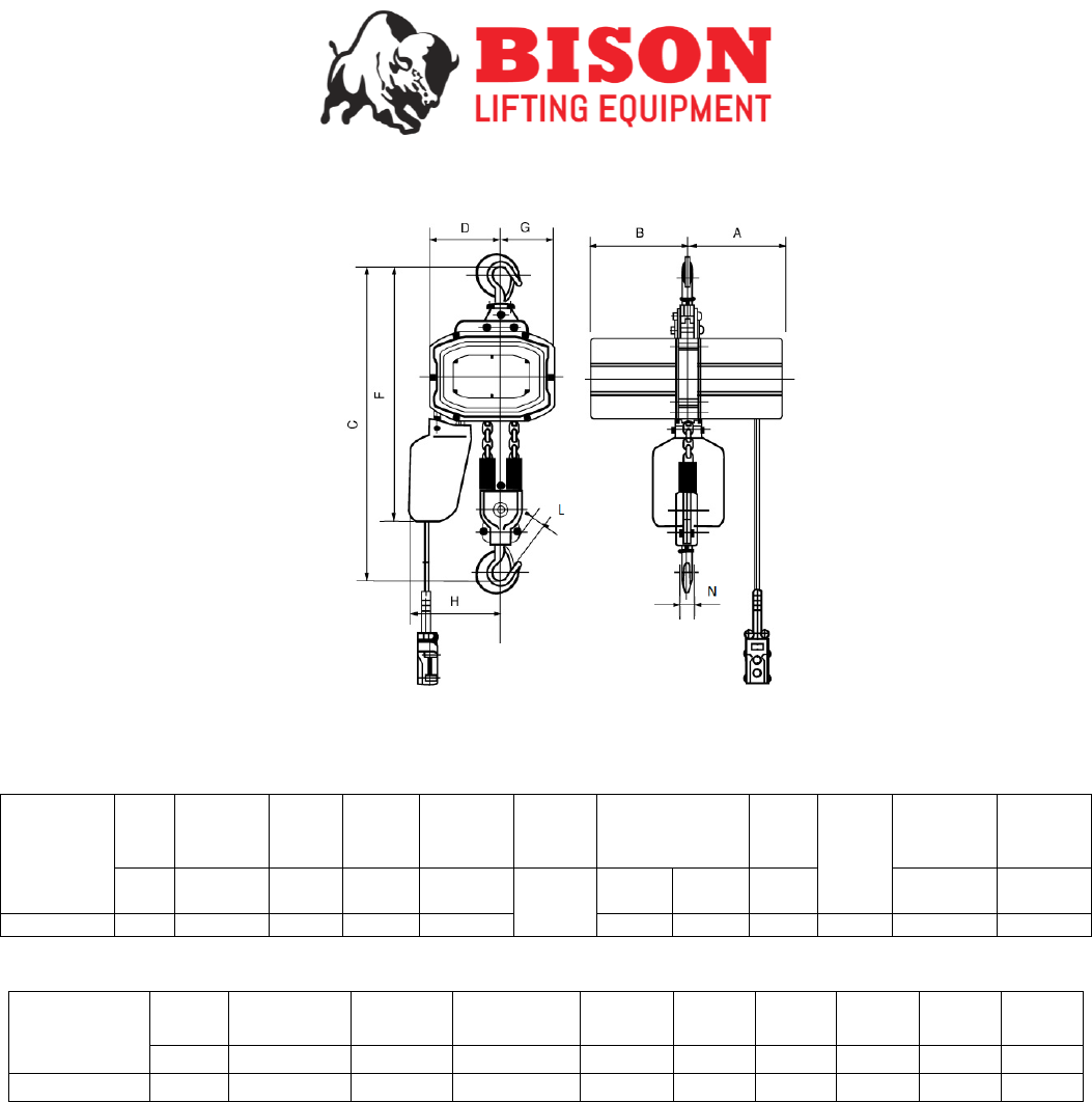
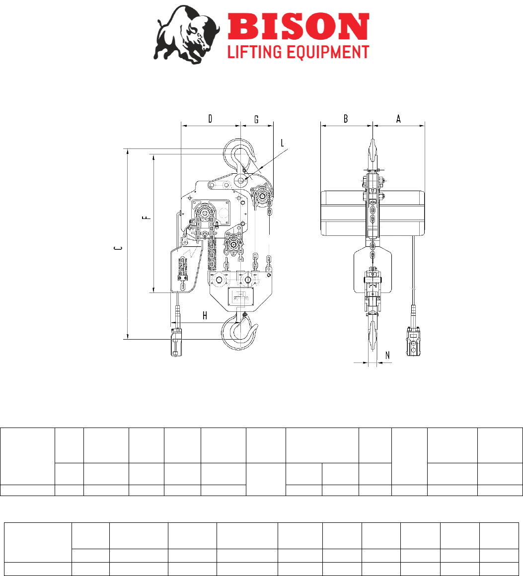
Product Code
Cap.
Head Room
(C)
A
B
G
D
L
F
H
N
Ton
Inches
Inches
Inches
Inches
Inches
Inches
Inches
Inches
Inches
HH-B20
2
29.1
10
10
7
5
1.65
26
9
0.83
2 TON
4
Product
Code:
Cap.
Standard
Lift
Height
Lifting
Speed
Motor
Output
Power
Supply
Control
Voltage
Rated Current
(amps)
Load
Chain
Size
Chain
Fall
Lines
Pendant
Cord
Length
Total Net
Weight
Tons
Ft.
Ft.
/min
Hp.
Volts (1-
Phase)
Volts
@115v
@230v
mm
Ft.
Lbs.
HH-B30
3
20
7
2
115/230V
24
14.2
7.1
7.1
3
17
198
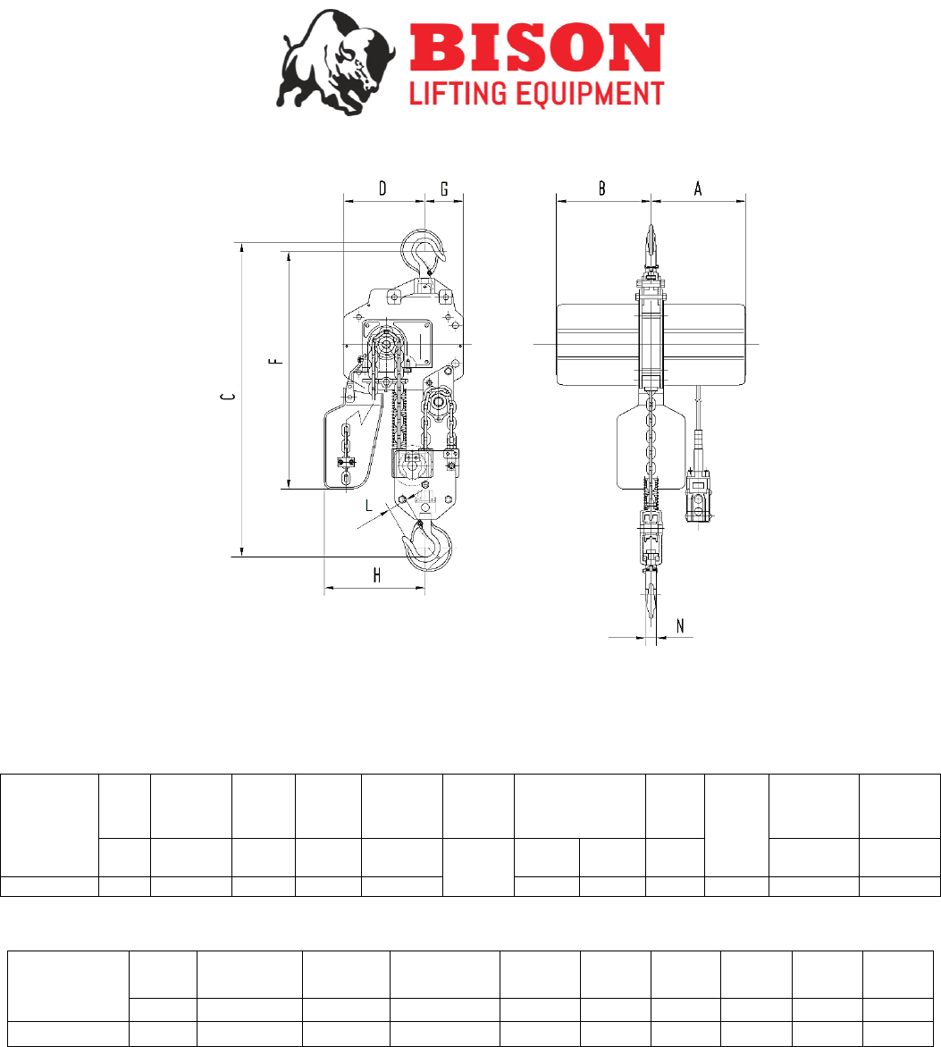
Product Code
Cap.
Head Room
(C)
A
B
G
D
L
F
H
N
Ton
Inches
Inches
Inches
Inches
Inches
Inches
Inches
Inches
Inches
HH-B30
3
31
10
10
4
8
1.69
28
11
0.90
3 TON
5
Product
Code:
Cap.
Standard
Lift
Height
Lifting
Speed
Motor
Output
Power
Supply
Control
Voltage
Rated Current
(amps)
Load
Chain
Size
Chain
Fall
Lines
Pendant
Cord
Length
Total Net
Weight
Tons
Ft.
Ft.
/min
Hp.
Volts (1-
Phase)
Volts
@115v
@230v
mm
Ft.
Lbs.
HH-B50
5
20
4.2
2
115/230V
24
14.2
7.1
7.1
5
17
333
Product Code
Cap.
Head Room
(C)
A
B
G
D
L
F
H
N
Ton
Inches
Inches
Inches
Inches
Inches
Inches
Inches
Inches
Inches
HH-B50
5
37
10
10
4
11
2.20
29
13
1.89
5 TON

6
Introduction
This manual is provided by Bison Lifting Equipment covering the safe operation and maintenance procedures for
the Electric Chain Hoist. This manual contains instructions on installation, general operating procedures and
maintenance instructions.
Contents
1. Electric Chain Hoist
2. Operators Manual
3. Warning Page
4. Test Certificate
Set-Up
Pre-Operation Inspection
After opening the crate, carefully inspect the hoist, load chain and chain container for damage that may have occurred
during shipment.
7
Installation
1. Install the hoist to a support structure. It is the user/ owner’s responsibility to ensure the chosen
support structure has the sufficient strength to support the hoist and the rated working load.
2. Connect the hoist to the appropriate power supply.
3. Before using the hoist, apply oil to the chain for easier operation and to prolong the life span.
4. To attach the chain bag/ container run the hoist until it is fully extended (DOWN) and then fasten the
bag/ container to the hoist. Once the bag is securely fastened feed the slack chain (non-load bearing)
into the bag/ container. Then run the hoist in the reverse motion (UP), guiding the slack chain into the
bag/ container (only applicable for those models supplied with the bag/ container)
5. Before proceeding to hoist an application to a dangerous height, test the hoist brake to ensure the
hoist can suspend and hold the weight from a safe height.

8
Operation
Hoisting: Install the hoist to a support structure. It is the user/ owner’s responsibility to ensure the chosen support
structure has the sufficient strength to support the hoist and the rated working load.
Do not attempt to lengthen the load chain in any way.
Do not attempt to repair the hooks as this could weaken them.
General:
1. The friction-clutch is designed to allow the first reduction gear to slip on an excessive overload. An overload
is indicated when the hoist will not raise the load. Also, some clutching noise may be heard if the hoist is
loaded beyond rated capacity. Should this occur, immediately release the raising control to stop operation of
the hoist. At this point, the load should be reduced to the rated hoist capacity or the hoist should be replaced
with one of the proper capacity. When the excessive load is removed, normal hoist operation is
automatically restored. [CAUTION: the friction clutch is susceptible to overheating and wear when slipped
for extended periods. Under no circumstance should the protector be allowed to slip for more than a few
seconds.]
2. Before picking up a load, check to see that the hoist is directly overhead. Avoid off-center loading of any
kind.
3. Take up a slack load chain carefully and start hoisting load gently to avoid shock and jerking of the load
chain. If there is any evidence of overloading, immediately lower the load and remove the excess load.
4. Do not allow the load to swing or twist while hoisting.
5. Do not allow the load to bear against the hook latch or the tip of hook.
6. Make sure the pendant cord is straight and is not tangled in the chain. Be careful not to snag the cord on
any sharp edges or objects.
7. When handling material that is being immersed in water, baths or any liquid, use a chain sling to prevent the
hook block from having to be submerged- this will stop any liquid from penetrating the bearing.
Precautions
- During overhead lifting operations, personnel should NOT stand beneath the suspended load.
- Prevent the load chain from dragging over sharp edges or corners.
- Be cautious of having fingers caught in the mechanisms.
- Do NOT leave a suspended load unattended.
- Do NOT attempt to lift people.
- Do NOT use the load chain to basket or choke a load.
- Do NOT drag or drop the hoist.
- Do NOT put the bottom hook through the loop of the chain. (only applicable on 2; 3 and 5-fall models)
9
Maintenance
The inspection procedure advised is based on ANSI/ASME B30.16. The following definitions are from
ANSI/ASME B30.16.
Inspection Classification
The inspection procedure is divided into two general grades based upon the intervals at which inspection
should be performed.
Hoist Service Duty
Duty
Average % of rated capacity
Normal
0 to 33%
Heavy
33 to 67%
Severe
67 to 100%
Special
Special Conditions
Frequent: Operators are to make visual inspections as often as required.
- Normal Duty Service – monthly
- Heavy Duty Service – weekly to monthly
- Severe Duty Service – daily to weekly
- Special Duty Service – recommend being inspected by a qualified individual before and after
each operation.
Periodic: Qualified individuals are to make visual inspections as often as required.
- Normal Duty Service – annually
- Heavy Duty Service – semiannually (twice a year)
- Severe Duty Service – quarterly
- Special Duty Service – recommend being inspected by a qualified individual before and after
each operation.
Frequent Inspection
The following is required to be inspected frequently:
- All functional operating mechanisms.
- Functionality of limit switch
- Hoist braking system
- Hooks in accordance with ANSI/ASME B30.10
- Hook latches
- Load chain
- Load chain reeving
10
Periodic Inspection
The following is required to be inspected periodically:
ANSI/ASME B30.16 requires all hoists subject to disassembly of load suspension parts, to undergo a load test
after re-assembly to pass full inspection.
Requirements of frequent inspection:
- Evidence of loose bolts, nuts, or rivets.
- Evidence of wear, corrosion, cracks, or distortion to parts such as load blocks, suspension housing, chain
attachments, clevises, coupling, suspension bolts, shafts, gears, bearings, pins and rollers.
- Evidence of damage to bottom block assembly.
- Evidence of excessive wear on motor or load brake.
- Evidence of damage of supporting structure/ trolley.
- Direction labels on pendant control stations.
- Warning label properly attached to the hoist.
- Load chain end connections.
- Evidence of wear, cracks or stretching on the load chain.
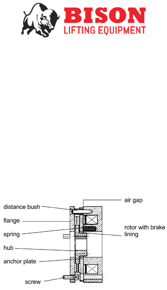
Brake Adjustment
• Brake Device: Should be checked and cleared of all dust and oil every three months. The air gap
should be no smaller than 0.3mm and no larger than 0.5mm. If the brake will not adjust, the brake
should be replaced before further damage or failure of the hoist occurs.
11
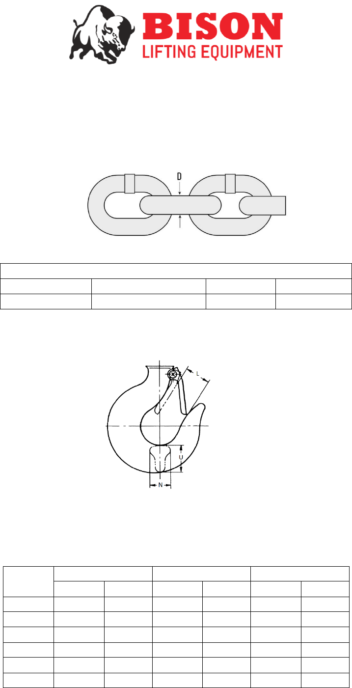
Chain Inspection
Inspect the chain for excessive wear, corrosion, or any cracks. If the load chain shows any of these signs, the
chain must be replaced immediately.
Using a Metric Vernier caliper, measure the distance of D to assess whether the wear of the load chain is within
the allowed tolerance. Refer to chart below.
It is vital that the chain be lubricated after every inspection.
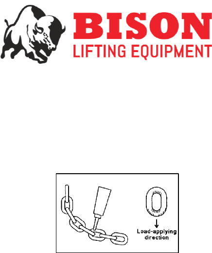
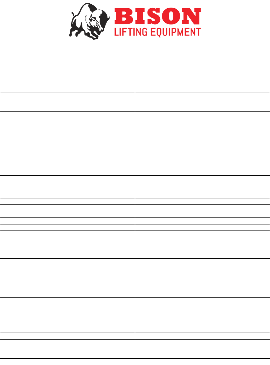
Hook Inspections
Inspect the hook for damage such as cracks, bends and excessive wear. While inspecting the hook, measure
points L, N and U. Refer to the table below to judge whether the measurement is within the tolerance or not. If
the measurement reads the value in the “Replace” column or lower, the hook needs to be replaced immediately.
Ensure the hook has a safety latch and that it is not bent or damaged that could result in an application to slip
off or out the hook.
Load Chain Wear
Hoist Capacities:
Inspection link intervals
Standard Size
Tolerance limit
¼, ½, 1, 2, 3, 5 Ton
5
7.1mm
6.4mm
Capacity:
Size of: L (inches)
Size of: U (inches)
Size of: N (inches)
Standard
Replace:
Standard
Replace:
Standard
Replace:
¼ T
1
1.47
1.10
1.03
0.73
0.65
½ T
1
1.47
1.10
1.03
0.73
0.65
1 T
1
1.47
1.10
1.03
0.73
0.65
2 T
1
1.65
1.30
1.22
0.83
0.75
3 T
2
1.69
1.37
1.28
0.90
0.83
5 T
2
2.20
2.68
2.60
1.89
1.81

12
Contactor Inspections
Recommended Contactor Replacement
Frequency of Jogging
Replace contactor after: (Starts)
Jogging is rare
1,000,000
during 25% of operations
500,000
During 50% or more or operations
200,000
Refer to the chart above for the recommend work rating of the hoist’s contactors. (Jogging: when the pendant
control buttons are pressed quickly and repetitively in to move the hook in small increments)
Records
Reports of hoist maintenance and inspections should be kept on record for reference and
maintenance scheduling.
General Maintenance:
• Gearing should be cleaned, and grease lubricated at least twice a year.
• Hooks: should be checked periodically for deformation and wear. Hooks should be replaced
immediately if signs of excessive rust, wear, cracks or deformation are shown.
• Ensure the load chain is kept straight and untangled when storing to prevent the chain from kinking or
twisting.
• Any hoists used out-doors should be covered up or stored in a clean dry environment when not in use.
13
Troubleshooting
HOIST NOT RESPONDING TO PUSHBUTTON/ PENDANT CONTROLLER
INCORRECT HOISTING DIRECTIONS
HOOK LOWERS BUT WILL NOT RAISE
HOOK RAISES BUT WILL NOT LOWER
Possible Cause
Remedy
No voltage at hoist-main line or emergency stop is
not released; fuse blown, or circuit breaker tripped
Release emergency stop; replace fuse or reset
breaker
Open or shorted wiring in the transformer; loose
connection or broken wire in circuit; mechanical
binding in contactor relay; pendant station
(pushbutton) contacts not closing or opening
Using a multimeter, test for electrical continuity and
repair or replace defective part.
Brake not releasing
Check input & output voltage of brake rectifier, check
brake airgap settings, if necessary, replace rectifier
and or brake coil.
Wrong voltage or frequency.
Be sure power supply corresponds to the hoists
required electrical specifications
Excessive overload
Reduce hoist load.
Possible Cause
Remedy
Connections reversed at either the control station or
terminal block.
Check connections with the wiring diagram
Possible Cause
Remedy
Excessive Load
Reduce Hoist Load
Loose connection or broken wire in the circuit;
pendant station contacts not being made; Upper limit
switch contacts are open.
Check the connections and contacts for sticking or
damage.
Start Capacitor damage
Replace the running capacitor
Possible Cause
Remedy
Excessive Load
Reduce Hoist Load
Loose connection or broken wire in the circuit;
pendant station contacts not being made; Upper limit
switch contacts are open.
Check the connections and contacts for sticking or
damage.
Start Capacitor damage
Replace the running capacitor
14
HOOK DOES NOT STOP PROMPTLY
HOIST OPERATES SLUGGISHLY
HOIST MOTOR OVERHEATS
HOIST IS NOISY
Possible Cause
Remedy
Brake Slipping
Check brake mechanism
Excessive Load
Reduce hoist load
Incorrect wiring of brake leads.
Check connectors with wiring diagram
Possible Cause
Remedy
Excessive load
Reduce hoist load
Low Voltage
Correct low voltage condition
Brake is not fully releasing
Check brake mechanism & air gap
Damaged run capacitor
Replace the damaged run capacitor
Possible Cause
Remedy
Excessive load
Reduce loading to the capacity of hoist
Low Voltage
Correct low voltage condition
Brake is not fully releasing
Check brake mechanism & air gap
Frequent jogging
Prevent frequent jogging
Excessive run cycles
Only operate the hoist within the duty cycle of the
motor: 40% ED
Unsuitable ambient temperature
Hoist must be operated in conditions no hotter 104°F
Possible Cause
Remedy
Noisy gears- excessive ear of gear; insufficient
quantity of grease.
Inspect gears. Replace gears or re-grease if
necessary
Incorrect incoming power supply
Check the voltage at the hoist for voltage
consistency, voltage spikes or drops can cause
damage to the hoist.
Noisy chain -damaged pocket wheel, excessive wear.
Twisted chain
Inspect the chain and pocket wheels for excessive
damage. Straighten the chain
15
LOAD CHAIN JUMPS ON SHEAVE
ELECTRICAL SHOCK WHEN TOUCHING THE HOOK OR CHAIN
Possible Cause
Remedy
Worn Chain
Inspect chain wear
Worn chain pocket wheel or sheaves
Replace parts
Twisted or kinked chain
Straighten and line up chain links
Possible Cause
Remedy
No grounding
Ground the grounding line in the power supply
Incorrect grounding
Check grounding terminal
Live part contacting to grounded part
Check electrical wiring and correct grounding if
necessary
Capacitor damage
Replace capacitor
16
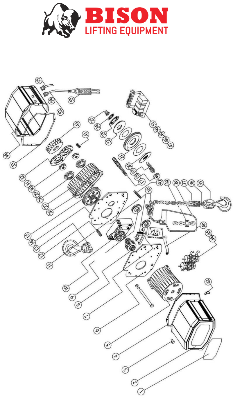
Electric Chain Hoist Drawings (¼T, ½T, 1T)
17
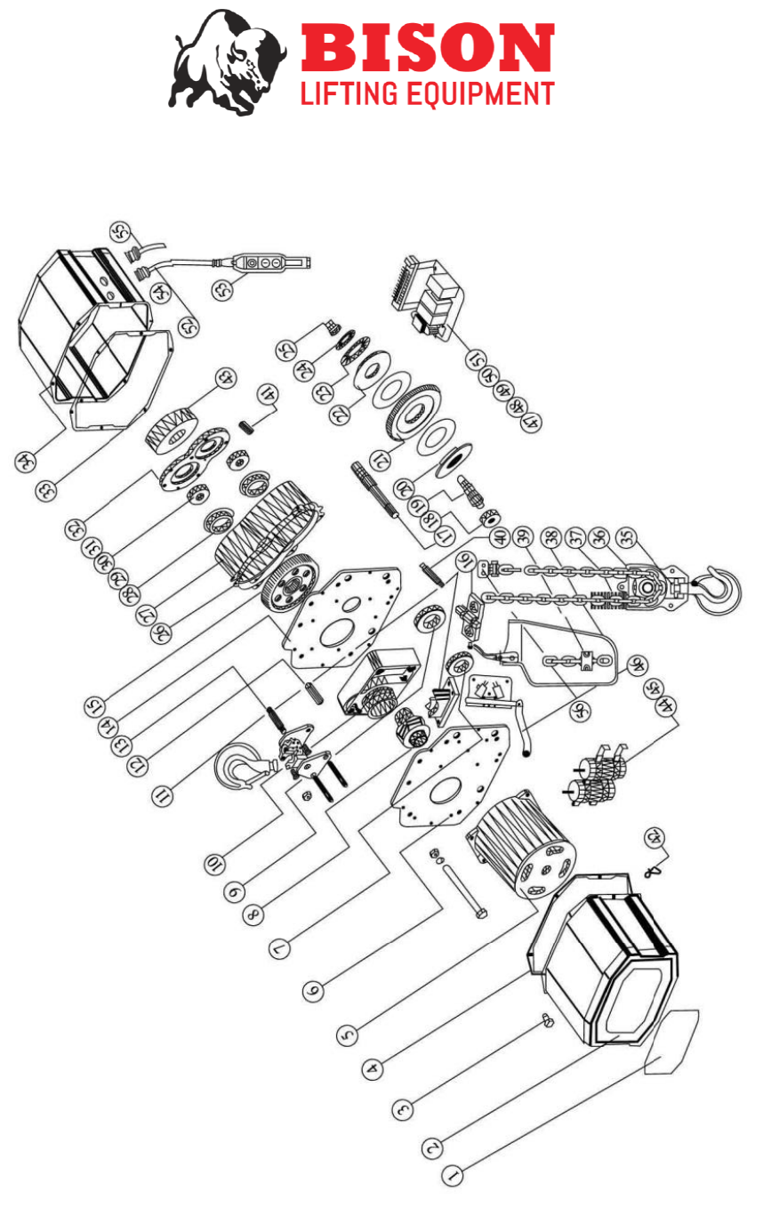
Electric Chain Hoist Drawings (2T)
18
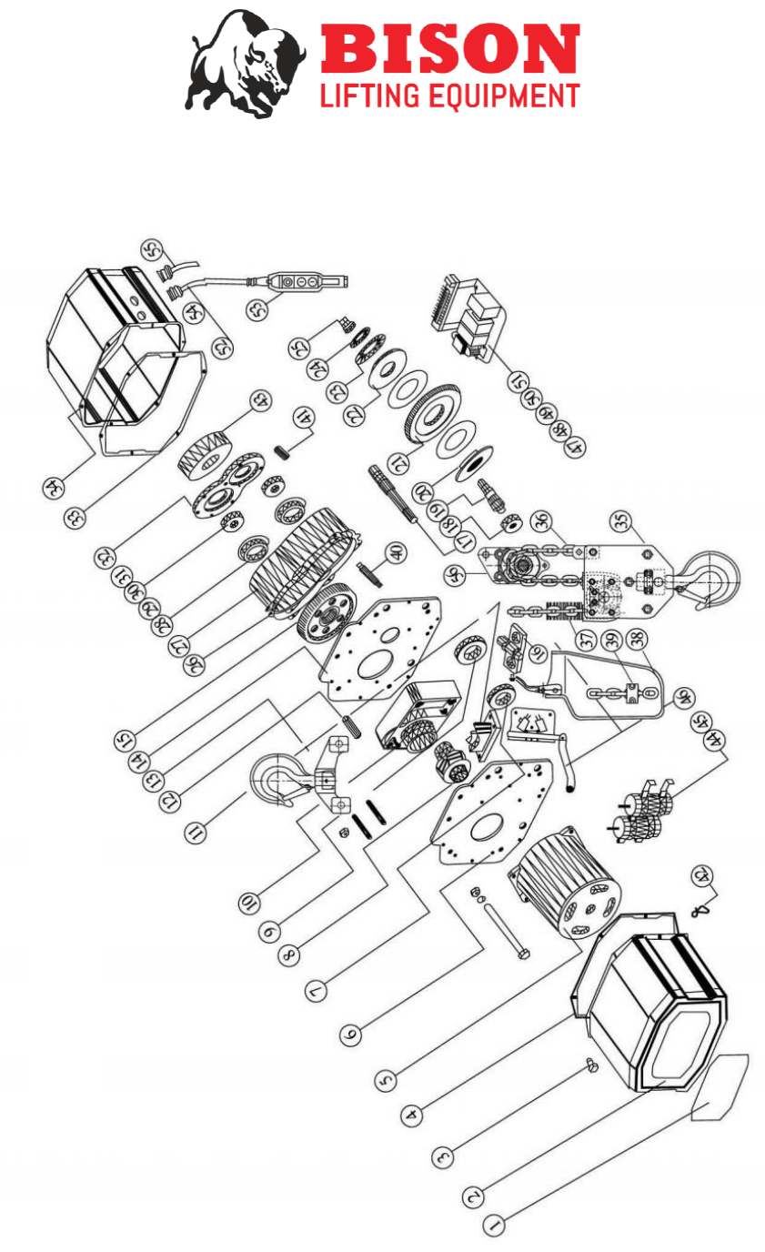
Electric Chain Hoist Drawings (3T)
19
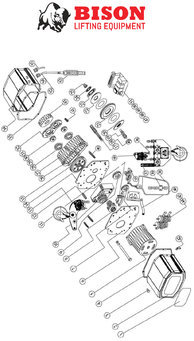
Electric Chain Hoist Drawings (5T)
20
Parts List
1
Name plate
31
Bearing
2
Cover
32
Coupling Plate
3
Hex Bolt
33
Hoist Gearbox Cover Gasket
4
Hoist Motor Cover Gasket
34
Cover
5
Motor
35
Bottom Hook Subassembly
6
Motor Mounting Plate
36
Load Chain
7
Bearing
37
Spring Buffer
8
Sprocket Wheel / Pocket Wheel
38
Chain Container
9
Bearing
39
Load Chain End Stop Clamp
10
Sprocket Wheel Housing
40
Connecting Pin
11
Chain Guide
41
Gearbox Housing Bolt
12
Conduit
42
Pendant Cord Strain Relief Clip
13
Top Hook Set Subassembly
43
Arrester Assembly
14
Gearbox Mounting Plate
44
Start Capacitor
15
Spline Gear
45
Run Capacitor
16
Limit Switch Actuator
46
Limit Switch Assembly
17
Driving Gear Shaft
47
Contactors
18
Bearing
48
Transformer
19
Gear Pin
49
Electrical Terminal
20
Clutch Set Plate
50
Brake Rectifier
21
Drive Gear Subassembly
51
Electrical Panel
22
Spacer
52
Control Cord
23
Spring Disk
53
Pendant Controller
24
Spring Seat
54
Cord Gland
25
Adjustable Nut
55
Power Cord
26
Gear Housing Spacer
56
Chain Fall Suspender
27
Gear Housing
28
Bearing Set A
29
Bearing Set B
30
Bearing
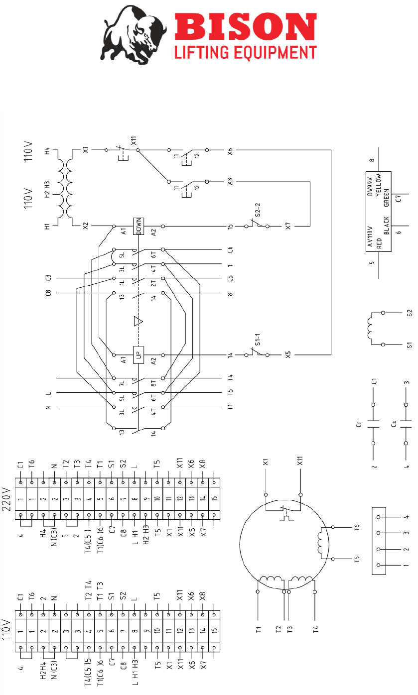
21
Electric Chain Hoist (Stop + Up + Down)

22
